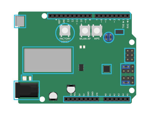
Power connector
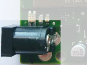
The coaxial power connector is compatible with every Arduino-Uno-compatible power connector. You can alternatively power your Connectino over the USB connector.
- Form factor: 2.1mm
- Voltage (recommended): 7V – 12V
- Voltage (limit): 6V – 20V
Micro USB connector

The micro USB connector powers the Connectino (USB standard: 5V). It can also be used as a Fallback to upload sketches.
Wifi status LEDs
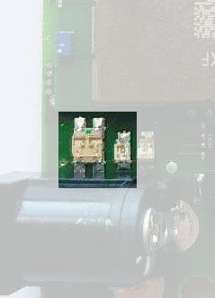
There are two wifi status LEDs, a bigger one on the outer side and a smaller one directly next to it.
The big one is the wifi-station-LED (staLED). It shows the IoT controller’s wifi connection state from a Connectino to an access point.
- staLED state:
- off: module off
- yellow: connecting
- red: connected
The small one is the status LED of the IoT controller’s wifi accesspoint (apLED).
- apLED state:
- off: AP offline
- blue: AP online
Reset button
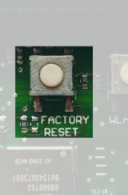
A short tap on the reset button restarts the whole Connectino, implying the IoT controller as well as the ATMega.
If you hold the reset-button for about 10 seconds, it will perform a factory reset on the IoT controller to the standard-configuration.
This will not reset the ATMega, so if you e.g. miss-configured the wifi settings with the Connectino-library and cannot connect to upload the scetch you will need to Upload your scetch via USB.
GPIO
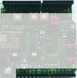
In most cases the general-purpose input/output ports are compatible to ArduinosUno-compatible hardware. The only exception as we know are Connectinos of the first revision. This board has 3V instead of 3V3, what can cause incompatibility with some (most shields still work with 3V) shields utilizing this voltage.

IoT Controller

The IoT Controller with our spezialized software forms the heart of the feature-rich Connectino. This is what connects to your network and provides all the IoT functions to the ATMega. It also includes the network interface controller (NIC) to which the MAC address is assigned. The MAC address is printed on the controller (see the picture below).

ATMega
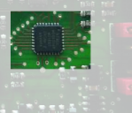
The ATMega 328p is the microcontroller, that also brings the Arduino Uno to life. This is where your sketches are executed and what e.g. controlls the GPIOs.
UART pins

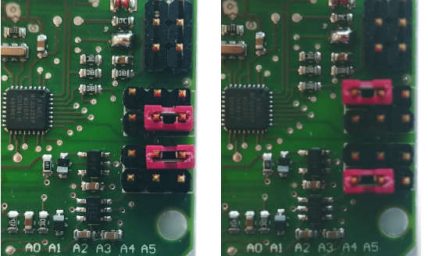
These are the pins that bridge between the ATMega, the IoT controller and the USB connector. On default the jumpers bridge the communication between IoT controller and the ATmega (both pictures on the right). If you want to enable the communication between USB and the ATmega instead, you have to switch the jumpers as shown on the picture on the bottom left.
Distance and light sensor
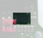
The VL6180X sensor on the Connectino is a good source for proof-of-concept tests to use a sensor without the need of extra hardware. We use it in a lot of our cloud tutorials. An easy example on how to set it up is the Arrow Connect Tutorial Code.
Sensor control jumper
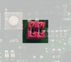
These jumpers connect the distance/light sensor to the I2C-bus to interact with those. If you have issues with other I2C devices and don’t want to use the sensor, just remove the jumpers.
ICSP


The ICSP port is fully compatible to the one of the Arduino Uno, the only thing you should bear in mind is, that it is rotated by 180 degree on the first revision of the Connectino.
